99cc HF Predator Modifications
| Note: This is not a step by step "how-to" for building the 99cc Predator engine. By no means is this intended to be a complete set of instructions for modifying this engine. You should always hire a professional engine builder before altering any engine from its factory condition. Modifying engines will void the warranty and could result in damage to the engine or even injury to the person operating the engine. |
 |
Here is Harbor Freight's 99cc Predator engine. We will be modifying this engine with AGK performance parts to see what kind of power we can pull out of this engine. We'll put this engine in a bicycle frame and compare performance both before and after our modifications. |
 |
We'll get started by disassembling the engine so we can pull the governor out. The exhaust and gas tank have been removed. |
 |
Next we remove this cooling tin from the top of the engine. |
 |
Now we pull the spark plug out. |
 |
Remove the six bolts holding the side cover. Pull the side cover out slowly. We pulled the side cover out about 1/2" and took a peak inside. The side cover gasket was stuck in one spot and we were able to salvage the gasket before pulling the cover all the way off and tearing the gasket. We also noticed the cam was going to come out with the side cover. This is not a big deal. The cam followers (lifters) and pushrods might fall out if the cam comes out but those can be put back in place later. It's also okay if the cam stays in place when you take the side cover off. |
 |
Now the side cover is all the way off with the cam sitting in it. You can see how the crankcase has some oil in it. The engines are started in the factory before shipping. You will want to clean out that factory oil along with any debris sitting at the bottom of the crankcase. |
 |
If the cam stayed in place when the side cover was pulled off it's time to take it out. We pulled the lifters (cam followers) out of the crankcase. |
 |
Remove the valve cover. |
 |
Remove the air filter cover. |
 |
Remove the air filter and guard. |
 |
Remove the air filter housing from the carb. |
 |
Remove the recoil starter. |
 |
Remove the governor spring. |
 |
Remove the throttle rod and spring. |
 |
Remove the fuel line. |
 |
Remove the blower housing. |
 |
With a 17mm socket and impact gun remove the flywheel nut. |
 |
The flywheel nut, starter cup and fan come off now. |
 |
In preparation for the next step thread the flywheel nut back on to protect the crankshaft threads. Thread the nut on to the point where it's just about flush with the crankshaft and then back it up about half a turn. You're going to hit this with a hammer and you don't want to hit the threads. |
 |
Now it's time to remove the flywheel. We use a large screwdriver in our left hand to apply some pressure against the flywheel. We put our left foot on top of the engine to hold it stable. With a hammer in our right hand we give the flywheel nut a good solid smack. This will break the flywheel from its taper. Make sure the flywheel nut is covering the threads on the crankshaft so they don't get damaged. This requires a good solid hit with the hammer. However don't hit it with everything you've got otherwise you risk damaging the threads on the crankshaft. |
 |
Once the flywheel breaks loose from the taper on the crankshaft you can remove the nut and the flywheel. |
 |
Remove the four bolts holding the cylinder head and take the cylinder head off. |
 |
Take the pushrods out. They may have fallen out earlier when the cam and lifters came out. Either way it's time to put them to the side. |
 |
Remove the head gasket. |
 |
Remove the two bolts from the connecting rod and take off the rod end cap. |
 |
Pull the rod and piston out of the bore. |
 |
With a hammer and punch remove the timing key. The timing key has a half moon shape so we just push it out with the punch from one side to the other. |
 |
Slide the crankshaft out. |
 |
Remove this nut and take the outer governor arm off. |
 |
Pull this pin and lower the inner governor arm out of the crankcase. |
 |
This pin holds the governor gear. Punch the pin into the block. |
 |
Here is the governor gear assembly. This one is actually out of a 6.5hp engine because we forgot to take a picture of the 99cc governor assembly. They are very similar. |
 |
There is a black washer where the governor gear was sitting. The washer almost never falls out with the governor. You need to reach up there and remove this washer. It's just sticking to the case with some oil between them. |
 |
This is the little black washer after it has been removed. |
 |
Now you have a bare block with only the coil still attached. |
 |
Now you can cap off this governor arm hole. Tap it for a bolt or seal it off with a different method. You just don't want oil leaking out of this hole. Also make sure your bolt does not interfere with the crankshaft inside the case. |
 |
Plug off this governor hole next. Be sure your bolt does not interfere with the crankshaft inside the case. |
 |
We removed the coil and gave the block a thorough washing. Now it's time to reassemble the engine. Install the crank first. You will want to inspect all the parts as they go back into the engine to make sure they are clean and not damaged in any way. Put a drop of oil on all the parts that make contact in any way. |
 |
Place the piston and rod in the bore next. Check the end gap on the rings and make sure they are placed in the 12, 6, 3 and 9 o'clock positions. Also make sure the triangle on the piston is pointing down toward the pushrod hole. |
 |
If you don't have a ring compressor you can use a popsicle stick to push the rings in. Apply a little pressure on top of the piston and gently press the rings in. |
 |
Install the rod end cap and tighten the bolts to 12 ft-lbs. Be sure to tighten the bolts evenly. |
 |
Install the lifters next. Everything gets a light coat of oil as we install these parts. |
 |
Now install the cam. Be sure the two dimples (timing marks) on each gear line up with each other. Don't move the cam and crank from this position once installed which will keep the piston at top dead center (TDC) for adjusting the valves later. |
 |
Slide on the engine side cover making sure it lines up with the two dowel pins. |
 |
Torque the side cover bolts evenly in a criss cross pattern to 8 ft-lbs of torque. |
 |
Install the cylinder head gasket. |
 |
Slide the cylinder head on. |
 |
Torque the head bolts to 22 ft-lbs. |
 |
Slide the pushrods in. |
 |
Loosen the rocker arm adjusters so you can position the rockers over the pushrods and valves. |
 |
With everything in position you are ready to set the valve lash. When you installed the cam you lined up the timing marks on the gears which would leave the piston at TDC. Hopefully you have not turned the crank since that step. If unsure you can look into the spark plug hole and see the piston. Turn the crank one way and then the other so you can see the piston move up and down. Make sure the piston is positioned all the way at the top. |
 |
Using a feeler gauge we set the lash at .006". Setting the lash is a tedious process. Once you think you have it at .006" you tighten the jam nut and the lash closes up. Keep adjusting until you have the lash set at .006". Once you have the lash set spin the crank over a few times and bring the piston back to TDC. Re-check the lash and make sure it's between .004"-.006". Adjust again if needed. |
 |
Once the valve lash is set you can install the valve cover. |
 |
We gap our spark plug to .035". The bigger the gap the bigger the spark. If you go too big the spark will not jump the gap. A large spark plug gap can also over work the coil so keep that in mind. |
 |
Install the spark plug. |
 |
Install the timing key back into the crank. |
 |
Slide the flywheel on. |
 |
The fan, starter cup and flywheel nut go on next. |
 |
Torque the flywheel nut to 25 ft-lbs. |
 |
This is one method we use to hold the crankshaft while we tighten the flywheel nut. |
 |
Install the coil. |
 |
Set the coil air gap to .020". Be sure both legs of the coil are set at .020" over the magnet. |
 |
Install the blower housing. |
 |
Install the recoil starter. |
 |
Install the inner air filter box. |
 |
Install the air filter screen and air filter. |
 |
With the air filter cover installed and the spark plug boot in place we have a complete engine ready to install in our bike. |
 |
Here's the 99cc engine mounted in our bicycle frame. |
 |
Now our exhaust is bolted up. This exhaust uses our laser cut flange and custom bent 1" tubing. We use a Briggs style (universal) muffler. |
 |
Time to setup the throttle linkage. Our throttle linkage kit consist of two "L" brackets, conduit retainer, return spring, wire stop (not pictured) and a throttle rod. |
 |
Start by loosening the throttle lever so it moves freely. We forgot to take this picture on our 99cc engine but you get the idea from this picture using a 6.5hp throttle assembly. |
 |
Drill a 5/64 hole in the throttle lever. |
 |
We use the spring hole on top of the carb which is a little further away from the pivot point and provides a longer throw. This hole needs to be opened up to 5/64 also. |
 |
Install the new throttle rod first. The side with the "Z" shaped bend goes in the carb and the side with the "L" shaped bend goes in the throttle lever. |
 |
Bend the "L" shaped side so it cannot come out of the throttle lever. |
 |
Bolt on the return spring "L" bracket. |
 |
Hook the return spring into the throttle lever. This can be adjusted later. |
 |
Flatten the other "L" bracket with a hammer. |
 |
Install the bracket here. |
 |
Twist this "L" bracket so the hole in the bracket is facing the hole in the throttle lever. It's difficult to see in this picture but on the left we have our twisted "L" bracket and on the right we are pointing to the hole in the throttle lever using needle nose pliers. |
 |
Install the conduit retainer into the "L" bracket. Now this retainer will be pointing toward the hole in the throttle lever. |
 |
Install the throttle cable. This may require some trimming and test fitting to get the proper length. |
 |
Install the wire stop. |
 |
Here is the complete throttle linkage installed. |
 |
Now we hooked up the fuel line, kill switch and filled the engine with 12oz of oil. |
 |
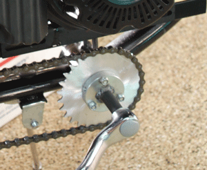
We discovered the output shaft is a little oversized for our 5/8 bore clutch. The output shaft is about .001" too large in diameter. So we're going to start the engine and hold some sandpaper over the shaft while the engine idles to bring it down in size. This could probably be done in a lathe before assembly but we're going about it garage mechanic style since most people don't have access to a lathe. |
 |
So after some sanding and test fitting back and forth our clutch slides on with ease. |
 |
Here's our completed bike ready for a test ride. There isn't anything special about this bike. We built it using some left over parts just so we can test the 99cc Harbor Freight engine. |
 |
This engine performed great on it's first test ride. We get some vibration upon clutch engagement but that can be tuned later. Once the clutch is fully engaged this bike rides very smooth. The engine has incredible hill climbing torque! We'll check top speed and rpm once we get a tach setup. The only engine modifications to this point are governor removal and a header. This is a great performing bike for around town. We're going to move forward with more engine modifications and see how well this engine can perform. |
 |
Now it's time to increase air flow. We are installing our UNI high flow air filter element. These air filters flow more air than the stock air filter and they keep the carb free from debris. Because they flow more air we'll have to increase the main jet size too. We start by removing the air filter assembly. |
 |
Next we remove the float bowl. |
 |
Here is the main jet. Remove this jet and replace with a larger main jet. We ended up testing a few different jet sizes and a #80 worked best here at sea level. The stock main jet is a #70. Put the bowl back on after the new jet has been installed. |
 |
With the carb back together you can install this portion of the air filter assembly. |
 |
For increased air flow we drilled holes in the air filter screen. This will allow more air to reach the carb while still keeping the air filter out of the carb. |
 |
The UNI air filter goes in next. |
 |
We also drilled holes on the outer filter cover to increase air flow. After trying the 5 large holes we think drilling multiple smaller holes looks better. Our UNI filter is not a color we care to show off. |
 |
The throttle travel from idle to WOT was a little short for our liking. When this engine is in a pressure washer or generator it will run at WOT for extended periods of time. So they design these carbs with a short throttle travel. To get a little more travel with our throttle we moved the cable and wire stop a little further away from the pivot point on the throttle lever. We bent up a tab at the end of the throttle lever and drilled a hole in it to achieve this. |
 |
With a tach installed we are ready to check our speed at different rpm levels. Here's what we came up with.
3600 rpm = 23 mph 4600 rpm = 28 mph 6000 rpm = 39 mphIf your 99cc Predator still has the governor in it the engine will only turn 3600 rpm. With the governor out of our engine it will easily spin up to 6000 rpm. We don't want to push it any further than this which will probably result in valve float. The biggest concern spinning this rpm is the stock flywheel. The flywheel was designed to spin 3600 rpm. Having the magnet come off the flywheel at high rpm is a scary thought. We are working on billet flywheels for this engine however it will take some time before those are made. At any rate, we are very happy with the performance from the Predator. We can cruise all day at 4400 rpm and we can reach 40 mph when needed. Climbing an 8% grade is no problem at all! |
 |
Now it's time to install a reworked carb with a larger bore size. |
 |
Wow! The new carb made a big difference. We were able to turn the idle down to 1600 rpm. The stock carb was happier at a 2100-2200 rpm idle. The biggest difference in power showed up from mid range on up to the top end. The engine even sounds crisper with this carb. Our reworked carbs work great with the 200cc engine too, but this little engine really responded well to a reworked carb. We took a plug reading and found that we were a little lean. We moved up to a #82 main jet. After taking another plug reading it looks like we can go a little bigger on the main jet. We will run this jet for a while and take another plug reading after we put a little more time on the engine. |
 |
We are very pleased with the performance of our Predator engine. We can stop the modifications here and be completely satisfied. Our bike has strong hill climb ability and will go 40 mph with ease. However, we're going to keep modifying and see how much power we can pull out of this engine. Next up is a custom ground .210" lift cam with 246* duration at .050". |
 |
To get ready for our camshaft installation we have removed the chains, clutch, chain guard and jackshaft. The oil has been drained from the engine as well. |
 |
Time to remove the six side cover bolts. |
 |
Wiggle the side cover loose and slowly pull it out. Save the side cover gasket if you can. The cam might come out with the side cover. If it does the lifters may fall out as well. |
 |
The side cover is off. Our stock cam stayed inside. |
 |
We removed the stock cam while holding the lifters in place with the other hand so they would not fall out. Then we put the new cam in place while still holding the lifters. You must be sure to line up the timing marks on the cam gear and crank gear. They are hard to see in this picture but the timing mark on the cam is in the 10 o'clock position. Just be sure those two dimples (timing marks) line up with each other. If your cam came out with the side cover and the lifters fell out just push the lifters back up in their bore and slide in the new racing cam. If the pushrods also fell out you can put them in from the top side before you adjust the valves. |
 |
Once the cam is installed you can put the side cover back on. Torque the six side cover bolts to 8 ft-lbs in a criss cross pattern. After the side cover is installed it's time to set the valve lash. With the timing marks on the cam and crank gear lined up your piston should already be at TDC. Use a feeler gauge and set the lash at .004". There are more details on setting the lash earlier in this article. |
 |
Install the valve cover. It's time to put spark plug and boot back in place too. |
 |
Now you can install the jackshaft plate, chain guard and clutch. Install the primary chain and adjust the tension. |
 |
Check sprocket alignment and install the secondary chain. Adjust chain tension. |
 |
Now fill your engine with 8oz of oil. After the engine has been filled with oil it's time to fire it up. For cam break in you can run the engine at 2500-3000 rpm for about 5 minutes. We're ready for a test ride. |
 |
With the new cam installed the first noticeable difference was the exhaust note. The engine is louder with a deeper growl than before. The engine runs smooth and the extra power really starts to pour on at about 3800 rpm. The engine has very impressive torque while getting on and off the throttle around 4000 rpm. We took a plug reading and ended up installing a #85 main jet. |
 |
It's time for this 99cc bike to go head to head with our 79cc two speed bike. The 79cc engine has a header, 22mm Mikuni carburetor, and the cylinder head has been ported. This bike did well against the 5hp Briggs bikes at a race on the Willow Springs track. The Briggs bikes had the power to pull away in the straights but we could catch up in the corners. With the two speed installed this bike had an advantage over the 5hp Briggs bikes on the Grange track. We love the Briggs bikes and their riders and certainly are not trying to say we're better than they are. We raced with them and I am able to use them as a baseline and comparison for our 79cc bike. So this will be a good match up for our 99cc bike. We started with a drag race from a standing start. Then we raced from a 3600 rpm roll and again from a 4600 rpm roll. Next we did a couple hill climb races. We switched riders and did it all again. The 99cc bike outperformed the 79cc two speed in all areas. Our 99cc Predator is exceptionally stronger on the top end. And even though the 79cc has the advantage of a lower gear ratio in first gear, the 99cc bike would still pull out front on the take off from a dead stop. We also noticed the 99cc thumper sound is much more aggressive when both bikes are running. It's sort of intimidating when you are full throttle on the 79cc bike and you hear the growl of the Predator storming up behind you. We can say the 99cc Predator has definitely responded well to our modifications. |
 |
We now have some time on the bike and have really been enjoying it. My son and I fight over who gets to ride it as this is our favorite bike to ride around town. It's time to push our 99cc Predator to the next level. The next step is to do some cylinder head work. We will port the cylinder head and if there is enough valve to piston clearance we'll mill it for extra compression too. We will also look into using the thinner 79cc head gasket for increased compression. |
 |
Here we have disconnected the fuel line and removed the carburetor. |
 |
Now we disconnected the secondary chain, tach, throttle cable, kill switch and header. |
 |
Now we have the engine out of the frame. |
 |
The valve cover and spark plug come off next. |
 |
The four bolts that hold the cylinder head have been removed and we pulled the cylinder head off. Taking the blower housing off first would help with a little added clearance. |
 |
Here's a look at the stock intake port. You can see the valve guide sticking up and it's difficult to see but the port to bowl entry has sharp edges. |
 |
Here is the cylinder head after it has been ported. We milled down the valve guide a little, cleaned up the port to bowl transition and did some work on the short side radius. The flow bench shows a good improvement after our work. |
 |
The stock head gasket on the left is .040" thick and the 79cc head gasket on the right is .010" thick. We're going to mock up the engine with the thin head gasket and measure valve to piston clearance to determine if we can also mill the cylinder head. |
 |
We discovered the piston is out of the hole more than the .010" thickness of the thin head gasket. So when we had the engine mocked up the piston came up and touched the cylinder head. So now we'll put the stock 99cc head gasket back on and measure valve to piston clearance so we can figure out if there is room to mill our cylinder head a little for extra compression. Note: The amount the piston comes out of the hole will vary from engine to engine. Some engines will even have the piston in the hole. These engines don't have really tight tolerances. |
 |
After using the clay method to measure valve to piston clearance we determined there is plenty of room to mill a little off the cylinder head. For starters we milled .050" off our cylinder head. A stock cylinder head is pictured on the left. Our milled cylinder head is on the right. Notice how the chamber on the milled cylinder head is now a little smaller. You can see how the edge of the chamber is now closer to the spark plug hole. Note: the stock cylinder head is 12.5cc's. |
 |
Our cylinder head is installed and our valve lash is set. |
 |
The engine is now re-installed into the bike and ready for a test ride! The cylinder head upgrade worked out great. We have more power on the bottom end with the added compression and the engine feels very strong on the top end with our port job. Unfortunately we are not able to push this engine to an rpm we would like to push it to. We are working with our vendors to produce a billet connecting rod and billet flywheel for the 99cc Predator. Once we get those two items we will increase the valve spring pressure and install some stainless steel valves with good retainers and keepers. The engine wants to keep pulling on the top end, but unfortunately we need to let off before something breaks. This 99cc Predator is a fantastic little engine and will receive more modifications as they become available. |
 |
One thing we wanted to note about our 99cc Predator bike is the installation of a small sprocket for the bicycle chain side. This is our 28t sprocket mounted to our mini hub. This makes it very easy to pedal the bike. Sometimes we have to pedal the bike in areas where we cannot have the engine on and we can do so effortlessly. You can't go fast with pedal power, but that's what the engine is for. The ease of pedaling has made this bike much more enjoyable that other bikes that are difficult to pedal. |
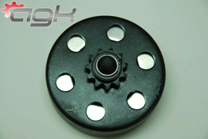 |
Earlier in the article we mentioned some vibration we experienced when the clutch would try to engage. Vibration is not only annoying, but can cause other issues with the bike, so here's the low down. There are two methods we use to reduce vibration upon clutch engagement. One way is to increase the stall of the clutch. The clutch we sell for the 99cc Predator has wedge shoes with a black spring which provides a 2800 rpm engagement. By installing regular shoes in our Max Torque clutch we get full lock up at 3100 rpm. This really smooths out the engagement and makes the bike so much more enjoyable. However you don't want a clutch with a 3100 rpm stall if you still have the governor in your engine. That would not give you much of a operating rpm range. The other way we smooth out vibration upon initial clutch engagement is by lowering our overall gear ratio. We are using a 12.12:1 gear ratio on this test bike. This ratio and the 3100 rpm stall on our clutch provides smooth engagement with little vibration. And as mentioned earlier in the article we have amazing hill climb ability and we can reach 40mph. The point we're trying to make is if you are using a high gear ratio of around 10:1 and you have a clutch that engages shortly after idle, you will experience vibration through the bike as that clutch is trying to engage. If you would like to smooth out that vibration you can use a lower gear ratio, increase the rpm engagement of your clutch or both! |